Calibrating the Sensors
Aiding sensors calibration allows the user to estimate the sensor parameters, to post-process them and to modify the project new values with the Delph INS Subsea calibration values. It is available for GPS and DVL sensors.
Definition and Recommendations for DVL calibration
DVL calibration means estimation of mechanical misalignment (Heading / Pitch) and estimation of scale factor.


Better results are obtained when the range to bottom is constant. This parameter can be displayed into the DVL_BT channel with ‘altitude’: For more information, refer to the Application Note - INS + DVL calibration.
Default parameters of the calibration
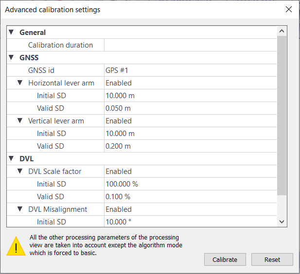
When selecting the advanced parameters option of the Calibration button from the Home or Processing view tab, the default parameters of the calibration are shown as follows:
Modifying the calibration parameters
Before starting the calibration, the user can modify the calibration parameters.
| 1. | Click on the Advanced Parameters sub-menu of the Calibration icon on the main menu. |
| 2. | Modify the parameters for the aiding sensor. |
| 3. | Click on Calibrate button to start the calibration with these parameters. The results are displayed on a new window following these rules: |
| > | The standard deviation is displayed in green (good) when it is lower than the valid SD |
| > | The standard deviation is displayed in orange (medium) when it is lower than twice the valid SD |
| > | The standard deviation is displayed in red (bad) when it is greater than twice the valid SD |
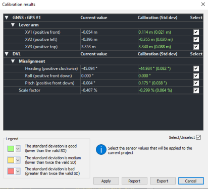
| 4. | Select the values to be taken into account in the project. |
| 5. | Click on Apply button to apply them to the current project. |
| 6. | Click on OK button to overwrite the project values with the calibration values. |
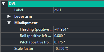
| 7. | The new values are displayed in the processing view: |
Starting the calibration with the default parameters
| 1. | Click on the Calibration icon on the main menu. The calibration starts with the default parameters. |
| 2. | The results are displayed on a new window: |
| 3. | Select the values to be taken into account in the project. |
| 4. | Click on Apply button to apply them to the current project. |
| 5. | Click on OK button to overwrite the project values with the calibration values. The new values are displayed in the processing view. |
|
To calibrate two DVL sensors: |
|||||||||||||

|
|
||||||||||||
Exporting the calibration parameters
Once the calibration is done, the user can export the calibration parameters in a XML file.
| 1. | Click on Export button then enter the name of the file. Click on OK button. |
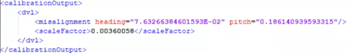
| 2. | Double-click on the file, the parameters are then displayed: |
|
|
The calibration output file could be imported in any project by righ-clicking on Load calibration output option in the processing view then the calibration output are displayed in this view. |
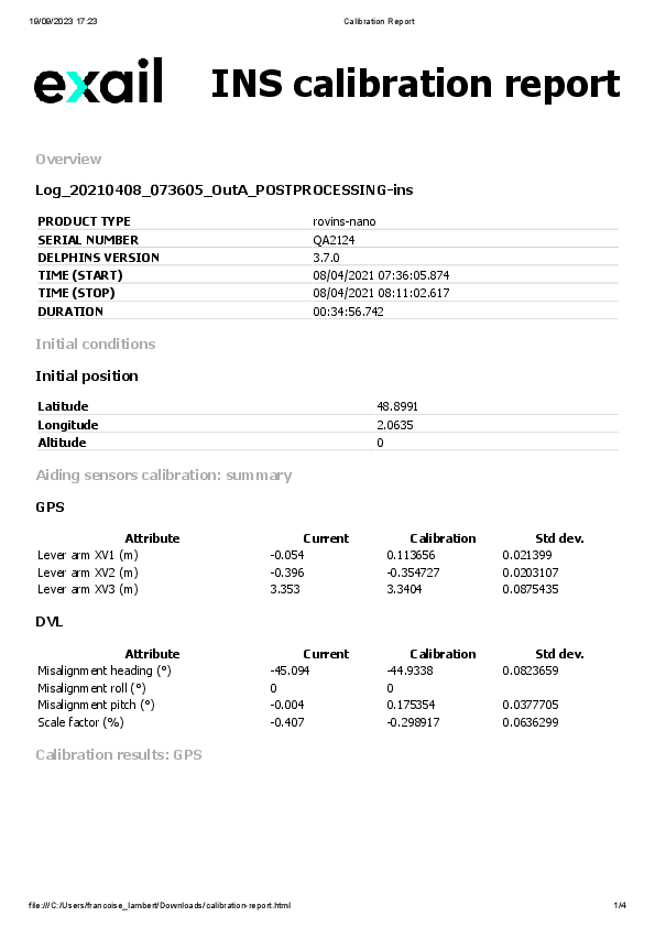
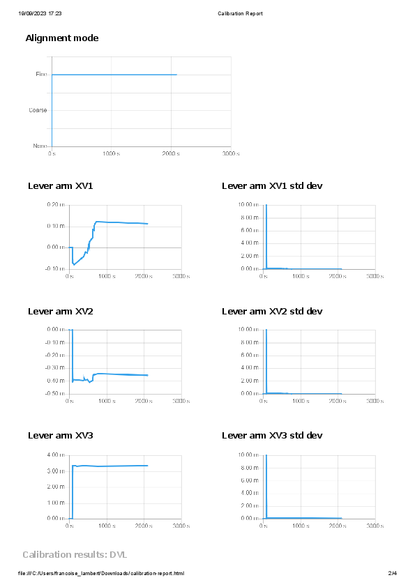
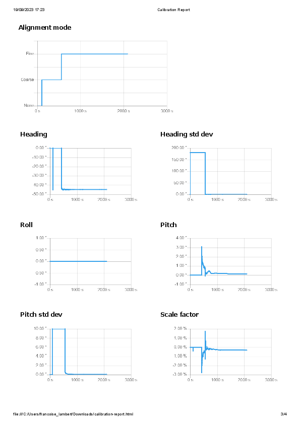
Launching the report of the calibration
Once the calibration is done, the user can get a report of the calibration.
| 1. | Select the values to be taken into account in the project. |
| 2. | Click on Report button then enter the name of the HTML file. Click on OK button. |
| 3. | Double-click on the HTML file and the data are displayed in the browser. |
Creating a batch file
| 1. | Click on the sub-menu of the Calibration icon on the main menu and select Batch file option. |
| 2. | Enter the name of the batch file then click OK. The file is created. Refer to Batch processing chapter to use this file. |
DVL Calibration Troubleshooting
|
Event |
Action |
|
DVL calibration stays to ‘coarse’ |
Check if the INS is already on fine alignment before the calibration or if altitude mode is maintained by depth or GPS. |
|
DVL calibration goes to ‘fine’ but doesn’t converge |
Check if the INS receives DVL Bottomtrack data during the whole calibration and has several GPS fixes at the end of calibration. |
|
DVL calibration is too long |
Tighten the DVL SD to 0.05 m/s, but check if neither GPS or DVL will not be rejected by INS. |
|
DVL calibration converge but scale factor error is too high (+/- 0.5%) |
Check if the INS has a SVS/SVP input sensor. |
|
DVL calibration converge but to an unsual heading error, above +/-1° from [0° + n*90°] or [45° +n*90°] with n=0;1;2;3 |
Check how the DVL is mechanically mounted accordingly to the INS. |