DVL
In the Processing panel at left, right click on a parameter and select Add Aiding Sensor then select DVL. The following instruction is added to the processing panel:
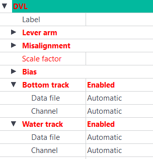
The values displayed in red must be entered.
| 1. | Click besides Label and enter a unique label. A Label is a free text enabling identification of a sensor when different sensors are used. |
| 2. | You can modify the lever arms of the sensor. This feature helps you to improve the accuracy of your navigation. Three offsets XV1, XV2, XV3 can be set. |
Enter the values of the XV1, XV2 and XV3 in the corresponding fields.

|
You can copy the DVL lever arm values to the primary output lever arm by right-clicking on the Lever arm fields. |
| 3. | Expand Misalignment and enter values for Heading, Roll and Pitch. |
The misalignment values between the INS and the DVL are computed during a calibration. Make sure to input the values corresponding to the calibration realized for your system. See appendix Calibrating a DVL Sensor for calibration procedure. More details may also be found into INS User Guide corresponding to the INS used into your vehicle / platform).
| 4. | Enter a value for Scale Factor. |
| 5. | Enter the values for Bias. Enter the values of the XS1, XS2 and XS3 in the corresponding fields. |
| 6. | Under Bottom Track, you may add a Data file and Channel. |
| 7. | Under Water Track, you may add a Data file and Channel. |
|
|
Default standard deviation for the DVL bottom track must be 0.2 m/s. Former versions of firmware had the default standard deviation set up at 0.5 m/s. Make sure to adjust the value if needed. |